PLEASE, BEFORE YOU PERHAPS WISH TO PRINT THIS FILE ASK YOURSELF IF YOU COULD POSTPONE THAT THOUGHT !
IT MIGHT STRIKE YOU AS SMALL AND SYMBOLIC GESTURE FROM YOUR BEHALF, BUT EVERY ACTION COUNTS. WE MUST START FROM SOMEWHERE !
PLANET THAT IS OFTEN CALLED AS WATER PLANET IN 2006. HAS 3% OF DRINKABLE WATER (NO TYPO) ISN'T THAT IRONIC?
WE NEED AIR EVEN MORE THEN WATER, CONSIDER THAT EVERY PAPER SAVING ACTION CONTRIBUTES TO LESS PAPER CONSUMPTION, THUS THREES AS SUCH !
RESPONSIBILITY IS THE ESSENCE IF YOU CONSIDER NEXT GENERATIONS, THOSE OF YOUR OWN KIN, YOUR CHILDREN, THOSE THAT INHABIT THE WOODS : ANIMALS.
SO READ THIS SCREEN IN NORMAL 030 MODE OR SAVE IT AS WEB PAGE ON YOUR OWN OS MACHINE.
You have now in your hands the most polished item proposed for the Falcon. The CT63 is the successor of the great CT60 that took many months of conception, design, tests and the 'know-how' of several software & hardware designers.
Material Overview :
The CT63 offers two modes : 030 and 060. The 030 mode (CT60 OFF) permits to keep a Falcon 100% as origin. With 060 mode (CT63 ON), it is too possible to boost the Falcon motherboard with some solders.
Features (in MHz) table of the different settings
| CT60 OFF | CT60 ON | |
| CPU | 030@16 | 060@60-100 |
| FPU | 882@16 or 32 | 060@60-100 |
| BUS (F30/CT60) | 16/OFF | 16/60-100 |
| DSP / VIDEL | 32 | 32 |
Software Overview :
The Hard Disk boot must be done with HD Driver 7.60 (or higher) or CECILE 2.18 (or higher). Don't use the old HDD drivers like AHDI, ICD & SCSITOOLS (HUSHI) if you want to not destroy your HDD partitions !
CECILE driver is not working with SCSI HDD and 060 !
External software :
AUTO Folder
Here is the order you must respect into the AUTO folder (use AUTOSORT prg). This is only indication because some of them can't be together !
- XBOOT
- MENU
- MAGXBOOT
- SETENV
- METADOS
- EXTENDOS
- DRVIN (replaces Fpatch2)
- SCC
- RSVX
- STING
- FDI_INIT
- JPEGD
- NVDI
- CKBD
- SPEEDOGDOS
- WDIALOG
- CENTSCREEN
- SLECTRIC
- UISIII
- FREEDOM
- LETEMFLY
- DESKPIC
- NOSYSTEM
- RDEBUG
- MINT
CPX
FILEINFO.CPX is an utility permitting to adjust 3 bits of program configurations and accessories: FastLoad, TT-Ram (Mem) and TT-Ram (Prg).
- The FastLoad bit prevents the system to erase all the memory to every launching of the software, that can take time with 64 MB of Fast-Ram.
- The TT-Ram bit (PRG) loads the program in Fast-Ram, attention to the software audio and video (by example : CUBASE AUDIO will not output sounds if the PRG bit is set ! But you should set the MEM bit).
- The TT-Ram bit (MEM) fact that the program will make this allowances memory in Fast-Ram, same remark for the program.
PATCHS
Some software need a patch or to be replaced by a patched version. It is the case with Cubase Audio that needs a patch present in the software package.
Précautions
Many components of the CT63 are sensitive to static electricity: avoid touching the card and especially the pins of the components and connectors. Hold the card by the edges. Please make sure your body is discharged of static electricity, example, touch a metallic object that is in contact with the ground (faucet for example), the best would be to touch a metal chassis (without paint) of an electrical appliance connected to the ground (toaster for example). Be careful with carpets and synthetic clothes... Don't walk barefoot on the carpet.
Warranty
The CT63 is warranted. However I can reduce or even cancel this warranty if the product hasn't been used or handled correctly.
Tools
- Phillips screwdriver.
- Thin flat pair of pliers.
Not furnished material
- SDRAM DIMM PC100 or 133 from 64 to 512 MB (see the table on the web site to choose).
- If you don't use an ATX TOWER :
- ATX Power Supply (with an AC ON/OFF switch is better).
- Femal 2 pins connector (HE13/14), 2 wires & push button to control the ATX power supply.
- If you want to turn OFF the CT63 with something else than a simple jumper :
- Femal 2 pins connector (HE13/14), 2 wires & lever button two positions (ON/OFF).
If you can't find the HE13/14 connectors, don't solder wires on the pin of the CT63 ! Let them clean ! Solder the 2 wires under the PCB on the solders of the connector; it's so better...
Compatibilité
The CT63 should run fine without solders with the 20 or 25 MHz motherboard boosters.
But it is depending of how the booster is managing the motherboard clock, especially the SDMA clock patch.
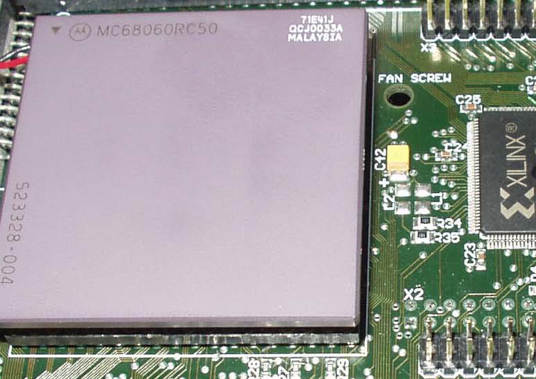
CPU & Thermic aspects
The CT63 is equipped with a cooler (heatsink + fan) on the CPU.
If you bought the CT63 with the 060, the heatsink is stuck to the CPU with thermical glue.
If you bought the CT60 without the 060, you have first to insert your 060 in the PGA area of the CT63. See the photo below for the correct position. If you do not insert correctly the 060, it will burn !
After you have to stick the furnished heatsink on your 060. Last, it is an absolute necessity to use thermical glue or the 060 may be dammaged by strong warming.
Orientation
The instructions and other placement indications are to be visualized and followed as if the mother board was in front of you, as if you were using the computer (in the origin case).
Undoing the Falcon
Flip over the machine, undo the 7 screws from the case and the 3 long ones from the floppy drive. Flip the machine over again and remove the case. Undo the power supply cover screws. Undo this cover. Disconnect the floppy drive power. Undo the 2 screws from the legs of the power supply, then remove the power supply along with the connector. Undo the screws of the cover remaining (all along the mother board), you will then bend the little tips straight up in order to remove this cover.
Plugging the CT63
- Insert your DIMM module on the CT63.
- Remove the jumper on the Falcon bus slot and keep it.
- Insert the CT63 on the Falcon bus. For this you need to place the card over the bus first to see if it is aligned correctly. Then apply an equal pressure with your left thumb on the solders of the left female connector and your right thumb on right female connector in order to fully insert the CT63. Attention: don't apply pressure on any of the CT63 components.
- Connect the Floppy power connector coming from the mb on the CT63 Four-pins connector at the right rear corner. ATTENTION : respect the colors indications : the wire RED with the pin indicated 'RED' on the board and same thing for the BLUE. Inverting the connector here will DESTROY THE MOTHER BOARD at POWER ON !
- Connect an ATX power cable to the Floppy power connector.
- Connect the ATX power main cable on the ATX power connector of the CT63.
- If you have a tower, connect the front tower wires (POWER ON/OFF and RESET push buttons, Power LED & IDE LED).
- Eventually, connect a switch CT63 ON/OFF (you can use the jumper from the slot to go back to 030 mode).
CT63 connector pinout (pin #1 at left) :
1 = ATX POWER Switch
2 = ATX POWER Switch Ground
3 = CT63 ON/OFF Switch
4 = CT63 ON/OFF Switch Ground
5 = IDE LED +
6 = IDE LED -
7 = RESET Switch
8 = RESET Switch Ground
9 = POWER LED +
10 = POWER LED -
11 = POWER LED -
12 = JTAG_VCC
13 = JTAG_GND
14 = JTAG_Key
15 = JTAG_TCK
16 = JTAG_TDO
17 = JTAG_TDI
18 = JTAG_TMS
Never connect something on the JTAG pins, except the JTAG download cable (see schematic on the web site update area). The LED don't need serial resistor : already on the CT63. The ATX POWER & RESET buttons must be PUSH buttons like on the ATX Towers.
The installation is done. Put the machine back together and test it.
Some problems to solve (with some solders) :
Yes, I know, this is no more a 'no solders' fitting, but it's difficult to do electronic update of old hardware especially when some old patches were not correctly done...
-
You hear some audio CRACs when running SDMATEST (2KB) at 50 KHz with 4 tracksAND/OR
- The machine is not stable.
WORK AROUND :
- Verify you see no 74F08 soldered (added) on the clock trace near the SDMA chip. If yes, you must remove this 74F08 and connect again the clock trace (that was cutted for this 74F08).
- On the GAL U63 (left of the NVRAM) : - If you see a component 74F08 or 74F04 with some wires connected on the resistor places R216, R217, R221 & R222, you must remove this component and the wires. Solder the three 33 ohms SMT resistors (furnished) on R216, R221 & R222 places. - If you have no 74F08 or 04 on U63, you have to verify all the three resistors R216, R221 & R222 are well 33 ohms marked 330 or 33R). On some motherboards, one of them can be a 0 ohm (marked 0 or 0R0) : replace it with a 33 ohms.
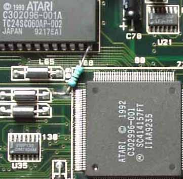
- Locate the SDMA (U36) under the floppy drive place. Locate the Clock trace arriving the the second pin from the left/rear corner (see the photo). Scratch the varnish (2 mm long) until you reach the metal, then tin it. Solder the 47 ohms (yellow, purple, black, gold) resistor (furnished) between the pin #14 of the AJAX chip (U20) and the clock trace like on the picture. The resistor must be closest to the SDMA and the pin soldered on the clock trace must be the shortest possible : it is termination resistor.
- RESET
delay at POWER ON (mode 030 & 060)Some ATX PSU may reveal this problem with a black screen.
WORK AROUND : Use a polarized capacitor of 22uF (or more) & 10V (or more) on C7 (or replace C7 with a 47uF or more) on the F30 motherboard near the RESET push button. Be carefull with the + & - pins (+ is on left to MIDI ports).
