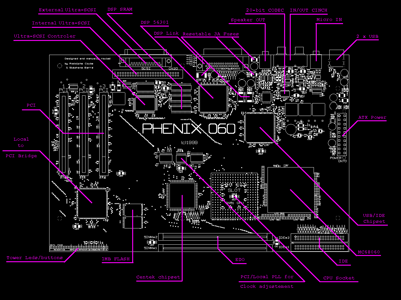
PHENIX 060


Logo by Chris Apers

Phénix Photo

The PHENIX 060 was designed from March 98 to July 99.

My routing was 100% manual with 4 layers and tooks 9 weeks.

The mainboard prototype was assembled at August 99, the 4th & 5th and was debugged up to September 99, the 29th.

I presented officially my PHENIX 060 at Hannover in November, the 19th & 20th during a computer show.

In december 1999, the PHENIX 060 project was killed by the three developpers of the OS (Dolmen) that announced they will not finish this last one.

The PHENIX is now defintively dead, after a birth in August 1999, the 11th, a coincidence, the day of a total eclipse of the sun in France.

Here are the last hardware modifications I did between APRIL 99 and JUNE 99:

  • Optimised routage of the motherboard near the 20-bit AUDIO parts, and on the PCI & IDE bus.
  • Added a HE14 connector for 2 fans (one for each 060).
  • Added a double programmable-PLL to select bus speed by software (local 060 bus up to 90 MHz & PCI bus up to 50 MHz).
  • Debugging of the arbitration logic for the 7 PCI agents.
  • Added 5V supply on CPU#B's slot.
  • Increased capacity of 32-Bit FLASH memory from 256 KBytes up to 1 MBytes (expandable to 2 MBytes).
  • Tweaks on demand of the motherboards mounter regarding to the size of the pads for the 2.2 uF & 10 uF SMD capacitors.


Evaluation for the first production of 100 Phenix : P60_Fab1.jpg (37KB) - P60_Fab2.jpg (51KB) - P60_Fab3.jpg (64KB)

Photos of the prototype debugging : P60_debug1.jpg (61KB) - P60_debug2.jpg (69KB)

Schematics of the AUDIO Circuit : P60_audio.jpg (29KB)

Chronograms of the EDO Ram accesses : P60_EDO.jpg (34KB)

Memory Map : P60_MemMap.jpg (57KB)

Films of Phenix PCB layers : P60_PCB_Films.PDF (1,2MB)

          Functionnal block diagram of the Alpine boards : P60_alpine.jpg (52KB)

          Layout of the ALPINE CT2 : Alpine_CT2.gif (10KB)

          Layout of the ALPINE P60 : Alpine_P60.gif (21KB)

Films of Alpines PCB : Alpine_PCB_Films.gif (169KB)


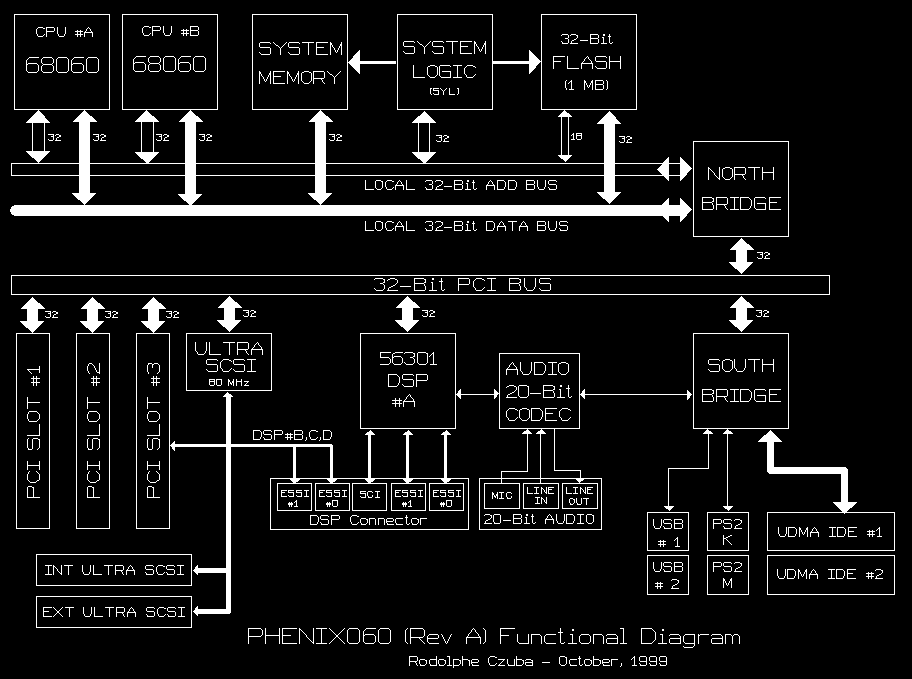
Architecture Diagram
 

Features

CPU MOTOROLA MC68060 at 80 MHz expandable to TWO MC68060 at 80 MHz (240 MIPS).
BUS CPU 060 32-Bit / 40 MHz (Half-speed mode).
BUS PHENIX PCI 32-Bit / 33 MHz.
RAM 2 SIMM sockets for up to 256 MBytes of 60ns EDO. BURST accesses (read/write) in 1 cycle at 40 MHz.
FLASH 1 MBytes & 32-Bit width containing the BIOS (SETUP/AUTOTEST/BOOT).
Upgradable to 2 MBytes for embedded applications.
DSP MOTOROLA DSP56301 at 100 MHz (100 MIPS).
  • PCI 32-Bit MASTER at 132 MBytes/s.
  • On-Chip Memories :
        - 2048 * 24-Bit of  RAM Data X.
        - 2048 * 24-Bit of  RAM Data Y.
        - 3072 * 24-Bit of  RAM Program.
        - 1024 * 24-Bit of  Instruction CACHE.
        -   192 * 24-Bit of  BOOT  ROM.
  • Off-Chip Memories : 384 KBytes 12ns SRAM (=128 kWords (24-Bit)).
  • Two ESSI at 26 Mbits/s.
  • External DSP connector (D-SUB HD44) for external peripherals.
  • It is possible to add 3 DSP daughter card on the PCI #3 and the pci #2 slots for a total of 7 DSP 56301 at 100MHz (700 MIPS).
USB
  • PCI MASTER at 132 MBytes/s.
  • 2 channels at 1.5 and 12 Mbits/s.
  • The SERIAL, // and MIDI ports are available by adding USB-SERIAL, USB-// and USB-MIDI(4in/4out).
ULTRA-SCSI (USCSI)
  • PCI MASTER at 132 MBytes/s.
  • SCSI bus maximum rate : 20 MBytes/s.
  • External Mini-SUB 50 connector.
  • Internal 50 pins connector.
  • Auto-Terminator on the motherboard.
VIDEO PCI S3 VIRGE DX with 4 MBytes of 35 ns EDO DRAM.
Drivers for others models will be developed.
  • 2D & 3D hardware functions used by the OS.
  • this card occupies one of the three PCI slots.
AUDIO ON-BOARD Stereo 20-Bit circuit at 44.1 & 48 kHz with the following on-board connectors :
  • 2 CINCH Inputs / 2 CINCH Outputs
  • 1 Mini-Jack for a microphone (ajustable gain). Accepts both asymetrical & symetrical models.
IDE (UDMA-33)
  • PCI MASTER at 132 MBytes/s.
  • 2 connectors for up to 4 IDE peripherals (DVD, ZIP, LS120, HDD, etc).
  • Maximum IDE bus transfert rate of 33 MBytes/s.
RTC Timekeeping + 256 bytes module with NVRAM (Non Volatile Ram).
Capability to suspend and wake up the PHENIX™.
INTERNAL SLOTS
  • 3 PCI slots (one is used by the Graphic card).
  • 1 direct access to the 060 bus by the CPU SLOT#B for :
    • diagnostic.
    • debugging link.
    • PowerPC™ card.
KEYBOARD & MOUSE Two PS/2 ports (Mini-Din 6).
CASE Standard Mini ATX 2.1 Tower.
OPERATING SYSTEMS DOLMEN
  • Multi-tasking
  • 100 % 060 ASM code !
  • AES & VDI emulation.
  • 2D/3D S3 VIRGE™ functions used by DOLMEN.
  • Easy to update by the FLASH.
  • RESUME function to get back the desktop and the softwares like you kept them at power off !
  • SCSI-1, 2 and 3 system managment (plug the peripheral and run).
  • HTML system managment for the documentations and the software online helps.
  • TRUETYPE vectorial fonts managment.
  • long name files managment.

LINUX 060


Implantation Diagram

Retour