Atari Sparrow resource page
This is my collection of Sparrow-related resources. So far it’s only the overview of its revisions and serial numbers but I have many photos and most importantly, two working units in my possession so I plan to update it in near future.
Sparrow revisions
There had been two revisions manufactured: rev.1 (usually on a hand-written label without the actual “rev.1” written) and rev.2 (more or less profesionally looking PCB).
The following list has been compiled from various Internet sources (eBay auctions, forum posts, computer history pages, …). Sometimes I had to extract the PCB s/n from its case s/n - although I’m fairly sure that the “algorithm” is correct, I do place a note where such s/n is presented.
As far as I know, only rev.2 PCB had its case available. The cases I have been able to find so far:
- A3 25 11 0010 09 (printed as “A3 25 11 00100 9”)
- A3 25 11 0010 11
- A3 25 11 0010 13
- A3 25 11 0010 15
- A3 25 12 0010 23
- A3 26 12 0010 33
- A3 26 13 0010 34
- A3 26 13 0010 35
- A3 26 13 0010 45
The fourth number (from the right) serves as an ID for the PCB (x=0) and case (x=1), as does the eighth number (1 = case, 3 = PCB).
rev.1:
- A3 22 23 0000 04
- A3 22 23 0200 06
- A3 2? 23 0000 07 (? is missing, perhaps a typo as it’s hand written?)
- A3 23 23 0000 13 (hand-written as “A3 23 23 00013”)
- A3 24 23 0000 17
rev.2:
- A3 24 33 0000 03 (printed as “A3 24 33 00000 3”)
- A3 25 31 0000 08
- A3 25 31 0000 09
- A3 25 31 0000 11 (“calculated” from the case s/n A3 25 11 0010 11)
- A3 25 31 0000 13
- A3 25 31 0000 15
- A3 25 32 0000 23
- A3 25 32 0000 25
- A3 26 32 0000 32
- A3 26 32 0000 33 (“calculated” from the case s/n A3 26 12 0010 33)
- A3 26 33 0000 34
- A3 26 33 0000 35
- A3 26 33 0000 37
- A3 26 33 0000 40
- A3 26 33 0000 45 (“calculated” from the case s/n A3 26 13 0010 45)
- A3 26 33 0000 48
- A3 26 33 0000 58
- A3 26 33 0000 59
- A3 26 34 0000 50
- A3 26 34 0000 53
It would seem there were three batches of both rev.1 (02/1992, 03/1992 and 04/1992) and rev.2 (04/1992, 05/1992 and 06/1992). Meaning of the second digit in “3x” is not clear, perhaps NTSC/PAL-I/PAL-B/PERITEL but that’s just a guess. For what it’s worth, the Falcon030 main board did exist in exactly these four variants: NTSC, PAL-I, PAL-B and Peritel.1
Number of Sparrows produced
This makes only 17 (rev.1) + 59 (rev.2) = 76 publicly known Sparrows in the world (assuming the numbering had restarted for rev.2). Actually, there were three Sparrow board without any serial number for sale, so that makes it 79.
Anfang 1992 wurde der Prototyp des Atari Falcon einigen Entwicklern präsentiert. Etwa 150 Vorserienmodelle wurden dann Mitte des selben Jahres an europäische Entwickler ausgeliefert. Einige dieser Rechner trugen das Label FX-1 wärend auf anderen der Name Sparrow prangte. Der Festplattentreiber des Prototyps meldete sich beim Booten mit “Sparrow” und benutzte den Blitterchip für den Datentransfer zur IDE Festplatte. Auf dem Board wurde ein TOS 4.00 in 2 Megabit großen DIL Eproms als Betriebssystem eingesetzt. In einer frühen Entwicklungsstufe war es sogar ein TOS 2.07, welches die VDI Routinen für die Bildschirmausgabe von Platte nachlud.
The Atari FX-1, or “Sparrow”, is also a prototype machine. Actually, it is almost a Falcon030. It has all its features except its true color mode (not fully implemented in the FX-1) and the PCM sound channels (12 bit instead of 16 in the Falcon).
These computers used the Atari Mega STe TOS (2.06) slightly modified to cope with the new graphic modes. This TOS version had the number 2.07 and was replaced in the last Sparrow models with the TOS 4.0 (The Falcon used TOS 4.01 in the earlier models, then the 4.04 and finally the 4.92 (never released)).
Atari produced less than 100 of these machines. They were built with sample spare parts and were used by developpers to write software for the future Atari Falcon.
Sparrow resources
The first four documents were found & rescued by Christian Zietz and first published at atari-home.de:
- Sparrow specification (dated Dec 18 1991) (converted into markdown by me)
- (Incomplete) Sparrow schematics (dated Mar 12 1991 - Sep 13 1991: Moshe Segal, John Horton) (converted into PDF by Christian)
- Falcon specification (dated Dec 3 1991) (converted into PDF by Christian)
- Falcon specification (dated Aug 26 1992) (converted into markdown by me)
- Sparrow schematics (dated Jan 19 1992 (recovered by Wizztronics)
- (Incomplete) Microbox gerber file
- Microbox PCB
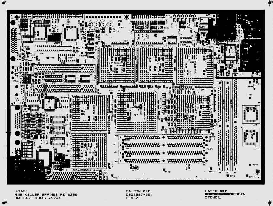
- Falcon040 stencil
- Microbox bill of materials (dated 02-05-1993) (the original file has corrupted item numbers and quantities; quantities recounted from the reference designators)
Sparrow vs. Falcon030 vs. Falcon vs. Microbox vs. Falcon040
Interestingly, there were four 32-bit machines (excluding the TT) developed (at various stage of completion) by Atari Corp. And their stories are much more intertwined than their names would suggest.
See also the related thread on atari-forum.com.
A lot of what follows comes from an archive of the technical publications department of Atari Microsystems in Dallas, Texas: the files of Marty Pennock who wrote the service guides for both the Sparrow and the Falcon between Oct’91 and Oct’92 - weekly status reports, memos, faxes, specifications, diagnostics source code and drawings. Footnotes marked TECHPUBS point to the files in this archive. I let Claude to summarise all of them into a human-readable story, I think it did a pretty good job with a lot of interesting facts.
1991: two teams, two computers
In 1991 Atari worked on two new computers on two different continents.
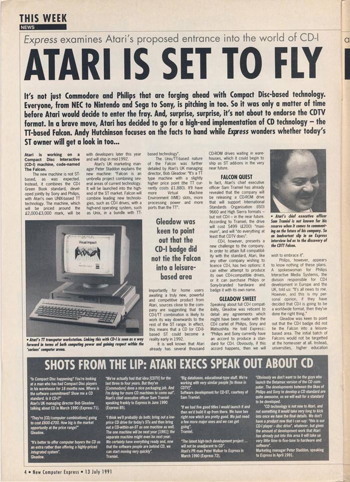
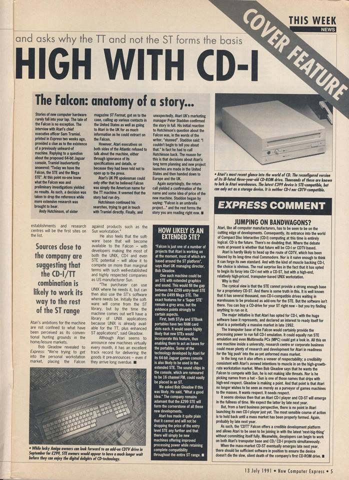
The Falcon was designed by John D. Horton Jr. in Dallas, Texas, as the successor of the TT. Its specification goes back to the definition of its “FBUS” from Oct 22 1990 and a first draft from Jan 4 1991.2 It was supposed to have full 32-bit data bus, 8- and 24-bit packed pixel (“chunky”) graphics, up to 32 MB TT (Fast) RAM, multi-slot VME bus, video and DMA I/O expansion slots, 68030+68882 and 68040 CPU support. In this magazine excerpt dated Jul’91 one can clearly recognise the TT/VME-based Falcon which had been in the works. It was expected to have a developer prototype by the end of 1991 and ship in mid-1992. Questions about its mechanical design were to be directed to Steven Chan and Ira Valenski (the former ST/FM designer).2
The Sparrow (designed by Moshe Segal and Eran Dariel in Israel) began its life in 1991 as a set of daughterboards for the STE to increase its sound and graphics capabilities - with the SDMA, COMBEL and STE Shifter (which would later become the VIDEL) respectively. There were rumours that this had actually been the goal all along - to create a powerful daughterboard for the existing STE line. It is not known if this is true and if it is, when exactly the transition to a real computer happened.
What the chip specifications from late 1991 do show is how much STE is inside the Sparrow. The “Sparrow DMA” (SDMA, dated Nov 4 1991) contains the ST’s ACSI DMA channel, modified to drive a 5380 SCSI controller and the 1772 floppy controller, plus a sound DMA for recording and playback which adds 16-bit stereo to the STE’s 8-bit modes.3 The new COMBO - already called COMBEL in the page headers - keeps the glue logic, the memory controller and the Blitter of the STE’s COMBO chip.4 The video part of that chip (sync generators, light pen) moved together with the STE video shifter into a new video chip, the VIDEL, which in Dec’91 promised 1 to 8 bitplanes with 6 bits per colour component, an “XGA high color mode” with 65,536 colours, a 16- or 32-bit video bus and pixel clocks up to 32 MHz. The STE’s Microwire interface for volume and tone control went from the video shifter into the SDMA.5 Eran Dariel’s “VTG Cook Book” from Dec 12 1991 explained how to program the new video timing registers, honestly admitting that some of its examples “were not tested yet”.6
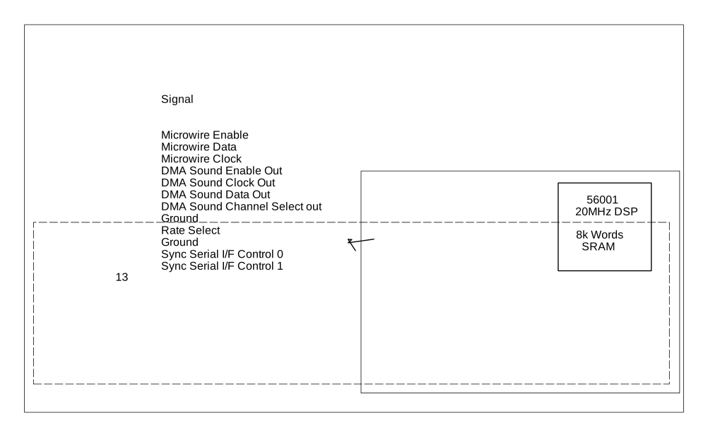
It is clear however that by Oct’91 the Sparrow was meant as a full featured 68000-based computer. The rev A10 of its specification lists how it grew up: the 68000 was changed to a 68030, an FPU and the 56001 DSP were added, ACSI was replaced by SCSI, the external floppy port was omitted, the video outputs were merged into a single VGA type connector, the audio output got “Walkman” jacks and the keyboard interface got hooks for “the new Atari Universal Keyboard Controller”. RAM still went into two SIMMs.74 The 68030 + 68882 + DSP were first available as a separate card, too - Sparrow’s diagnostics speak about an “030+DSP sparrow board” and an “SP030D card” as late as the beginning of Feb’92.8 A (partly damaged) drawing from Feb’92 even shows a DSP board with a “56001 20MHz DSP” and “8k Words SRAM”, connected via Microwire and the DMA sound signals - the FX-1 already had its DSP running at 32 MHz with 32K words of SRAM.910
Focusing on the Sparrow computer naturally lowered priority to its competing project, the Falcon.
Winter 1991/92: the Sparrow arrives in Dallas
Both machines met on the desks of Atari Microsystems in Dallas. In Nov’91 the Dallas office had only “an A8 release of the product spec, but no schematic” of the Sparrow and asked Moshe Segal for more.11 In December it received a Falcon schematic and the Sparrow specification from Israel, in January the Falcon product specification, and by Jan 9 1992 the first chapters of both the Sparrow and the Falcon service guides were written.1213
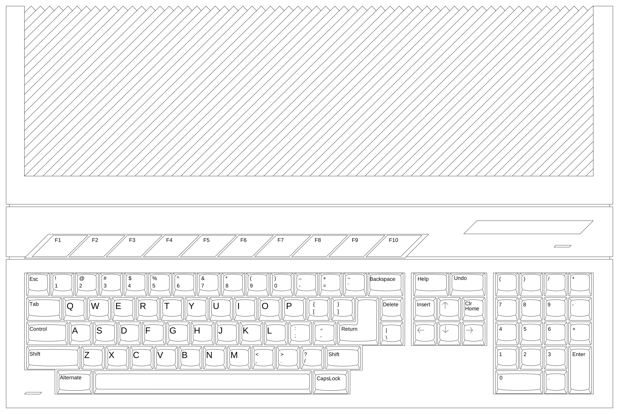
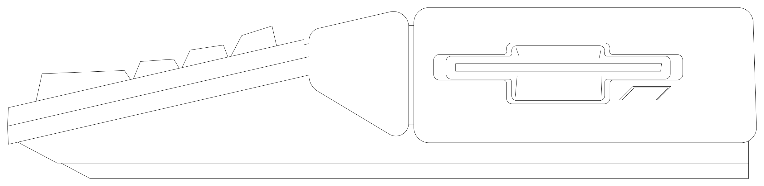
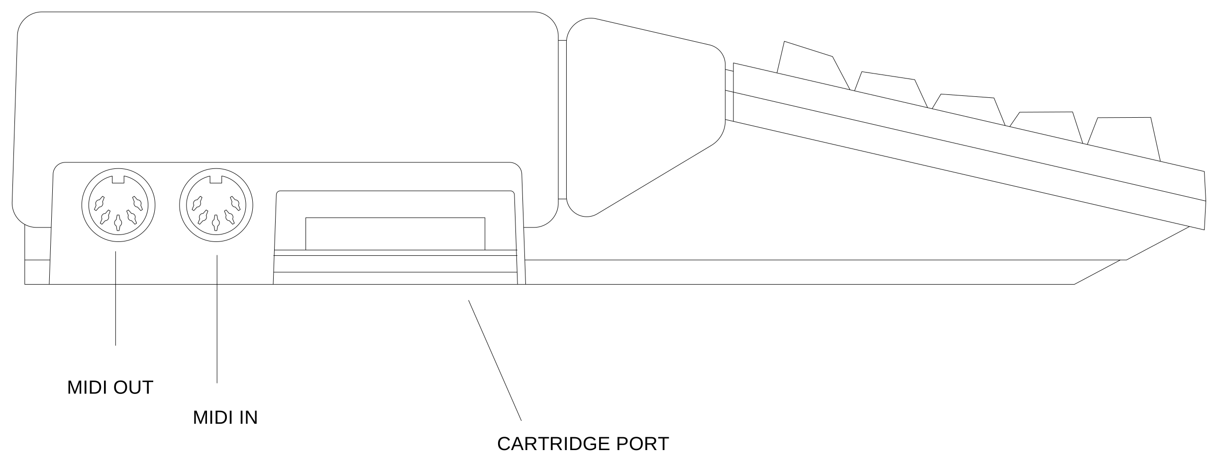
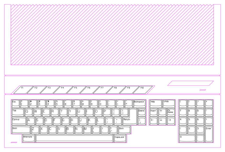
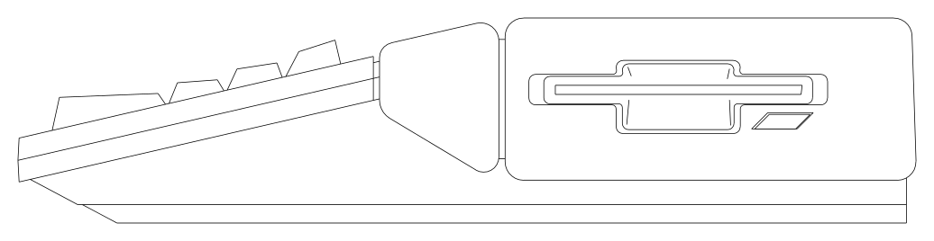
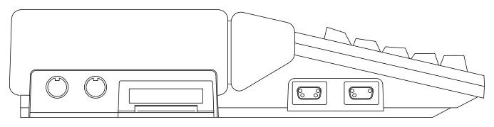
The Sparrow proved to be a moving target. Its “schematic changing too much to do a good service guide”, the specifications were “not very good. Many holes and information lacking” and the schematic revision A1 “does not match spec”.13 Dallas had to ask Israel again for the COMBEL and VIDEL specifications and for the pin list of the new 26-pin DSP connector.11 Richard Miller from Atari Sunnyvale came over to Dallas to work on the Sparrow, all Sparrow connectors got their part numbers at the end of January - for the new 19-pin monitor connector “The male connector spec does not exist as yet.” - and the mechanical drawings for the case arrived in February.1413 The case didn’t start from scratch: the drawings of the Sparrow’s keyboard top and right side are the ones of the STE+ from Oct’91 (an STE with a “DOS compatible hardware AT emulator using an 80286 microprocessor”) and only the left side with the enhanced joystick ports and the rear panel were drawn anew.15
In mid-December 1991 Roy Stedman started writing the Sparrow’s production diagnostics, based on the STe diagnostics. Their changelog shows the hardware changing under his hands: “NOW ONLY 68030’s NEED APPLY” on Jan 31 1992, “TOS 2.06j USA” added to the ROM test on Feb 5, yet “Hacked up for 68000 Sparrow” again on Feb 18, and on Apr 9 simply “NO ACSI ON SPARROW.”8
Early 1992: the FX-1
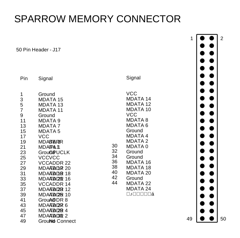
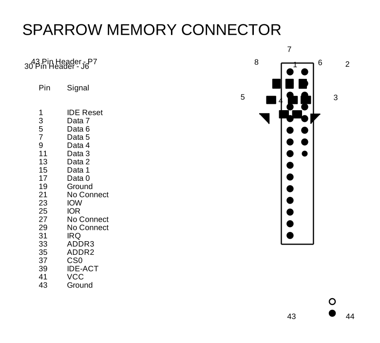
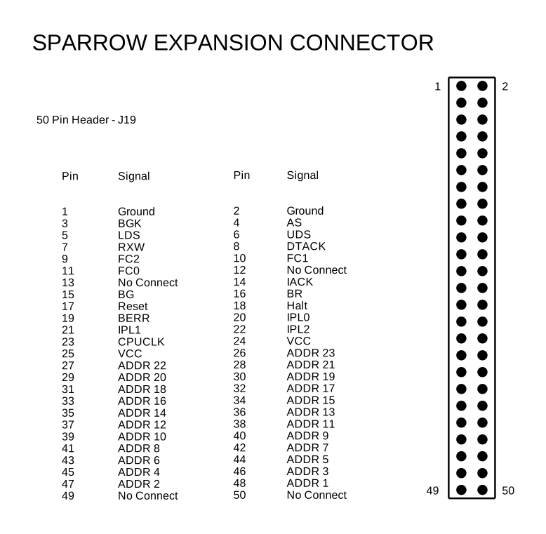
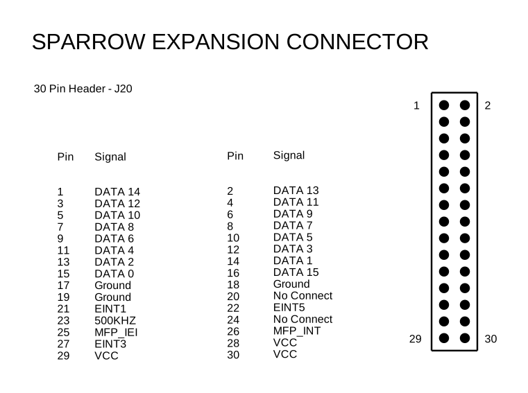
In Feb’92 the machine got its first hardware reference guide - under the name FX-1 (versions 0.3 and 0.4 from Feb 16 and Feb 18 1992, written by “RGM”).10 The SIMMs were gone, replaced by a custom memory module with 1 to 14 MB, TOS sat in two 256 KB ROMs and the true colour mode existed only in 320x200, either with 15 bits plus a genlock bit or with 16 bits - which fits the “not fully implemented” true colour mentioned above. Sound mixed old and new: sixteen bit DMA recording and playback of up to ten tracks, but only 8-bit ADCs, 12-bit bitstream DACs and a dedicated DSP (not the 56001) just for volume, bass and treble. Microwire was still there, even on pins 1-3 of the new DB26 DSP connector. The connectors were mostly those every Falcon030 owner knows (MIDI, parallel, SCSI II, DB19 video with genlock support, headphone and microphone jacks, DSP connector, RF modulator, enhanced joystick ports) but the serial port was driven by the MFP just like on the ST, the LAN port was a 9-pin MiniDIN and the DSP’s SCI port was “not implemented in FX-1”.10 The memory board plugged into a 50-pin (J17) and a 30-pin (J6) connector and the internal expansion port with its 68000-style bus used a 50-pin (J19) and a 30-pin (J20) connector - exactly the connectors every Falcon030 memory board and expansion card uses.1617
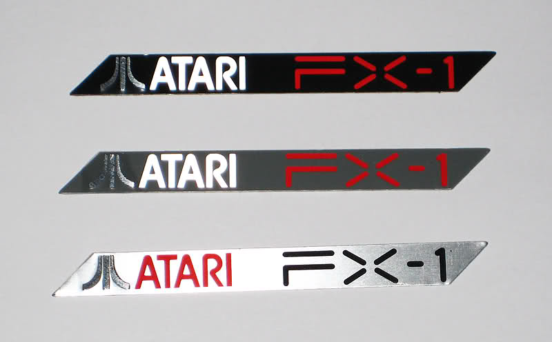
As the first Sparrow rev.1 motherboard’s manufacturing date is Feb’92 it is very likely that this is what Atari showed in Mar’92 at CeBIT in Hannover – and announced it as the Falcon shortly after. The new name was ready by then: Toomey Freeman’s “FALCON 030 DIAGNOSTIC SPECIFICATION” is dated Mar 3 1992 - and the machine it describes is still the FX-1 inside, with the PSG sound going “to the RASCAL device” whose tone and volume are set “via the MicroWire bus” and a serial port driven by the MFP. Its appendix, a test fixture for the expansion port, was designed by Tom Le.18
Spring 1992: developer machines
The rev.2 boards followed from Apr’92 on while the COMBEL chip was being revised in the meantime: the “rev. 1 combel” confused the FPU detection, showed “mixed and out of order color bars” and couldn’t do the Sparrow’s VGA 320x400 XGA mode. The diagnostics were adapted for “Rev 2. Combel’s” in June.8
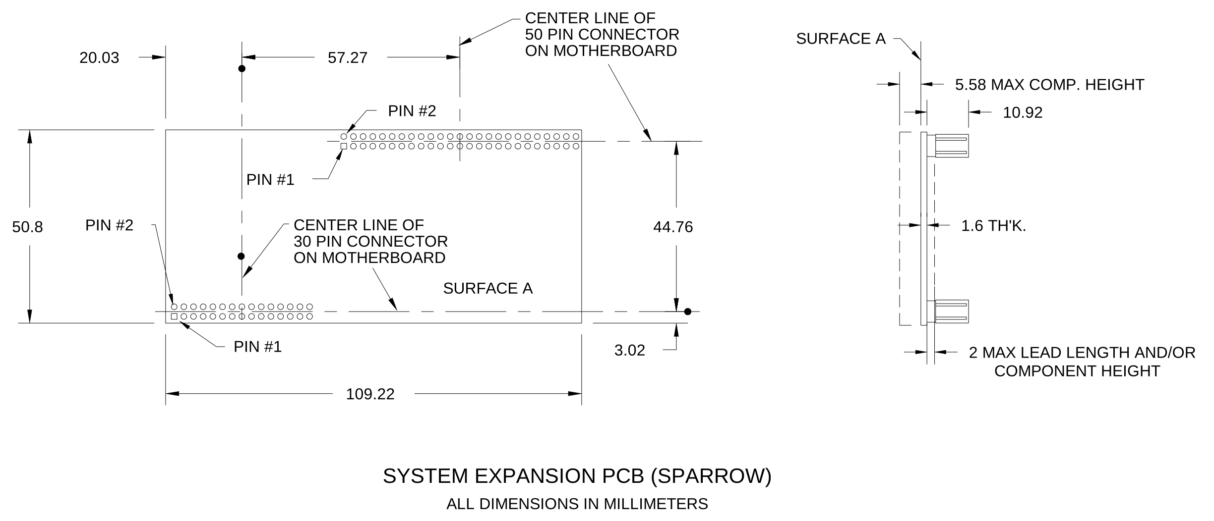
Developers received the Sparrow in a “developer support package”. Its introduction (Apr 23 1992) starts with “Welcome to the first developer support package for Sparrow” and describes a machine with 16 MB of RAM and a 40 MB hard disk which could boot from the hard disk only with a boot floppy in the drive (“this will be changed in the next set of ROMs”). It started into a command shell where one could choose between the STE video modes and “two of the many new Sparrow modes” loaded from disk - 320x200 in true colour or in 256 colours, with NTSC timing and better without the Blitter in true colour. This matches the TOS 2.07 loading its VDI from disk from the German quote above. The package also contained guidelines for MultiTOS applications and for games which were expected to use the enhanced joysticks (“CX-40 style controls should not be supported”) and 640x480 in 256 colours.19 In June Richard Miller got drawings from Dallas “for use at developers meeting in UK” and Bill Rehbock in Sunnyvale got the drawing of the “SYSTEM EXPANSION PCB (SPARROW)”, a board of just 109.22 x 50.8 mm.2021
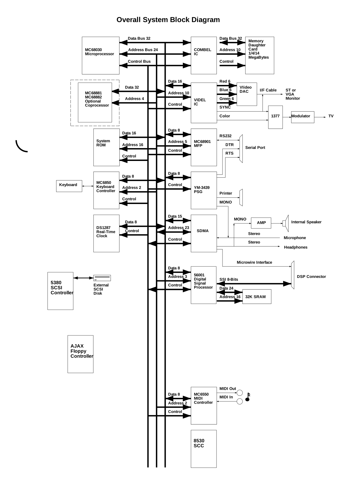
The Sparrow’s block diagram from Apr 6 1992 still shows the serial port on the MFP and a “Microwire Interface” going to the DSP connector.22 The accompanying “Developer Hardware Release Notes” from Apr 29 1992 are the best description of what the Sparrow was still missing.23 The developer machines had 8-bit ADCs and 13-bit DACs with “VERY poor sound quality” (though “programs like Quartet seem to work OK”) while production machines would get a 16-bit codec. Microwire “has gone away on production machines”. An old version of the memory controller prevented true colour in 640 pixels on TVs and in 320 pixels on VGA monitors. The serial port was connected to the MFP instead of the SCC, memory access took five 16 MHz clock cycles instead of four, the DSP host port sat at different addresses and there was no connection matrix between the DSP, the sound DMA and the DAC/ADC. Production machines would also add the Acknowledge and Select lines on the parallel port and support 300 DPI mice. Two more differences were left as a puzzle: “I’ll buy a beer for the first developer to spot them.”
In May’92 the hardware reference guide was renamed to “Falcon030 Hardware Reference Guide” (version 1.0a from May 11 1992) but otherwise it still described the FX-1, including its 9-pin LAN port and memory modules now “1 to 16 MBytes”.24 The power supply specification from May’92 still carries the Sparrow name (“117 VAC SPARROW PSU SPECIFICATION”, 37.4 W) - and its part number C302866-001 is the one of the Falcon030’s 117 V power supply later.251
Summer 1992: the Sparrow becomes the Falcon030
Over the summer the Sparrow was turned into a product, with engineers in Dallas and Sunnyvale deeply involved. In June Dallas had a “rough draft from J. Hoenig that contains many errors” about the SDMA changes with “J. Horton working hard to resolve issues”, in July John Hoenig and Tracy Hall (Sunnyvale) faxed the “latest FALCON030 schematic changes”, Scott Matson delivered new VIDEL and COMBEL specifications and John Horton the new SDMA specification.20 In the diagnostics source code, Roy Stedman commented on the new audio test: “Horton wants to do FFT’s on it. I don’t.”8
What changed on the way from Sparrow to Falcon030:
- The SDMA grew from 120 to 144 pins and “The MICROWIRE interface has been deleted from the current design” - only its registers were simulated so that older software wouldn’t lock up. The sound DMA now fed a codec clocked from 25.175 MHz for 50 kHz, the number of tracks went down from 10 to 8 and a digital PSG was planned but “The prototypes and probably early systems will not have the digital PSG available” so the YM’s analogue output went into the codec instead. A new pin told the chip whether a 68030 or a 68000 bus master was active: “Some day (Sparrow++++) this will be an output.”26
- The 8-bit ADCs and 13-bit DACs gave way to the 16-bit codec. On the first rev 3 boards the “ASCO CODEC shuts up occasionally while playing” and the solution was to “use Crystal part”.27
- The COMBEL grew from 144 pins to a 208-pin package, all mentions of SIMMs disappeared and it got the same 68030/68000 bus master pin as the SDMA.428291
- The serial port moved from the MFP to the Z8530 SCC (the diagnostics were converted on Jul 7 1992) and the DSP host port moved once more, to the consecutive addresses $FFFFA200-$FFFFA207 of the rev 3 boards - the diagnostics know three different layouts.8
- RAM ended up on memory boards with 1, 4 or 16 MB of which “only 14 Mbytes of RAM may be accessed” for STE compatibility. The factory tested the boards with a 14 MB card while the systems shipped with a 1 or 4 MB board.1729
- TOS moved from two ROMs into a single 4 Mbit EPROM in a PLCC socket.101
- The expansion port kept its connectors but got new bus grant signals and the BMODE pin; “CPUBGI and CPUBGO must be connected together on production machines in order that they work at all” which the factory did with a jumper from J20 pin 20 to pin 22.2329
- The product specification still names the HD6301V1 keyboard controller with an “Option for interfacing to the new Atari Universal Keyboard Controller” but the rev 3 boards were tested “with new keyboard”, the diagnostics know a keyboard revision called “COPS” and the parts list from Oct’92 has keyboards “W/COP888” - some of them still called “K/B FX-1”.1781
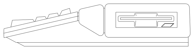
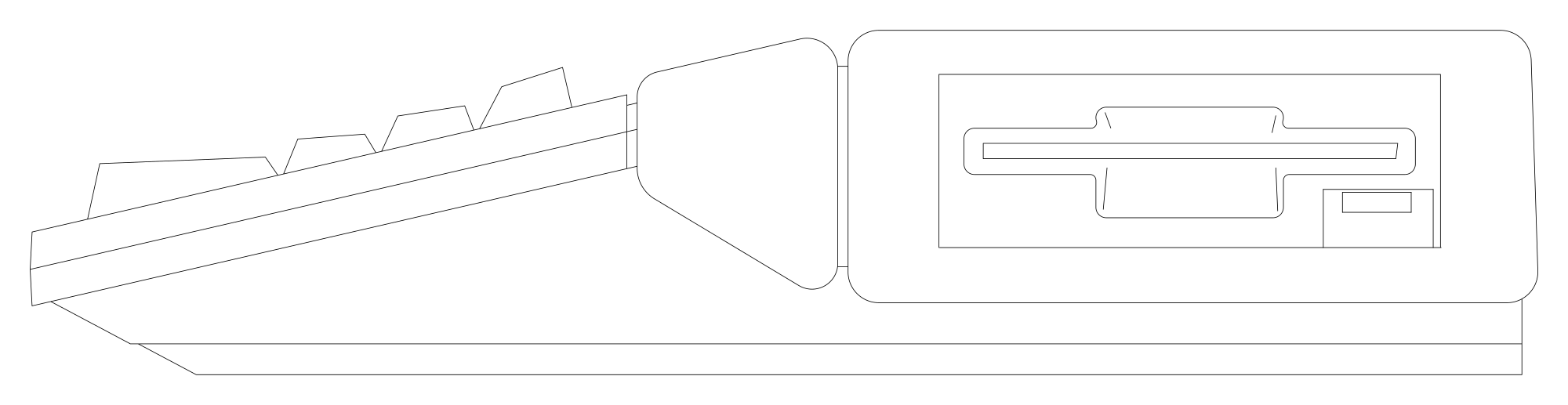
- Even the case got a last touch: on Jul 23-24 1992 the floppy side was redrawn with a new drive bezel, first with the old slanted eject button and a day later with a rectangular one.3020
The diagnostics call the boards “Falcon030, rev 2” and “rev 3”. Work on the rev 3 boards started on Jul 9 1992 and Roy Stedman’s list of their problems from the very next day reads like a typical first batch: shorted address and size lines, audio capacitors shorting the 9 V or 5 V rails “(no solder mask)”, a solder short under the DSP’s SRAMs, a missing resistor silencing the speaker and an open trace killing the FPU.27
The production was prepared in Taiwan. A preliminary FALCON030 product specification was written “to go with you to Taiwan” on Jul 13 1992 (for Tom Ulaszek of Dallas product engineering), the “FALCON 030 PRODUCTION PROCEDURE” draft by J. Smith is dated Jul 15, all assembly drawings went “to Jerry Smith in Taiwan” on Jul 29 and in August the corrected hardware specification followed “Tom in Taiwan”.20 The production procedure describes board burn-in, TOS installation, system aging and a safety test, and its incoming inspection lists the chips “COMBEL AT4181” and “SDMA AT4182” and the hard disks CP2044, CP2064, CP2084 and ST9051A with more models still waiting for a part number.29
The “FALCON030 Hardware Product Specification” reached rev B on Aug 10 1992.17 Even though the offical Falcon030 release happened in Aug’92 at Atari Messe in Dusseldorf (with TOS 4.00), Atari magazines got for their September issue only photos of Sparrow’s typical dark grey case with white ST/E keyboard and rev.2 motherboard inside. A month later all the Atari press were previewing the real Falcon030. In Dallas, Marty Pennock began printing ten copies of the FALCON030 Service Guide on Sep 24 1992 and under his plans he wrote just “Get a job.”.31 The guide itself is dated Oct 1 19921 and the production diagnostics, “Sparrow Production Diagnostic Rev. 1.12” in July, were archived as version 1.19 in September.832
But it took several months (as late as Mar/Apr’93!) until the Falcon030 hit the stores due to “insurmountable quality control issues”. This was also the time when the internal HDD got upgraded from 65 MB to 80 MB and TOS from version 4.00/4.01 via 4.02 to 4.04. Eric Smith’s progress reports date the last steps: TOS 4.03 ROMs were burned for production in early March 1993, two weeks later he “Changed version number to 4.04” and by May 1993 he “Built a new version of TOS for Falcon, containing our combined single/multi tasking AES and the new VDI, BIOS, and GEMDOS”.33
So basically the Falcon030 is a bugfixed version of the Sparrow with a few removals: the Sparrow still had the Microwire interface, the so called RASCAL sound chip (able to process only 12-bit samples) and an MFP-driven serial port - none of which are present in the Falcon030.
1992: the Falcon becomes the Falcon040
Meanwhile the Dallas Falcon went its own way. The service guide chapter written in Dallas in Jan’92 already describes it as a 68040 machine at 33 MHz with VMEbus and a power supply of “Approx 130 watts.”34 - although at that time there was “No ASIC documentation for Falcon chips” as “They have not yet been written.”13 The first chip specifications from Feb’92 still keep both options open: the IO controller has bus modes for the 030 and for the 040, takes “Functions from the TT SCU chip” and creates an 8 MHz 68000-like bus for the ST/TT compatible peripherals. And the sound was still the Sparrow way: the DMA controller feeds “the RASCAL sound chip” with Microwire registers, adding 16-bit stereo at 44 and 48 kHz.35 The specification’s own history shows a sixth draft on Feb 21 1992, a “Prototype A release” on Apr 8 1992 and a “Prototype B release” on Aug 26 19922 - by then it got the DSP, 16-bit sound DMA and DSP connector and even got rid of the Microwire.
The Falcon borrowed from the Falcon030 here. In July John Horton handed over new specifications for both the Falcon030’s SDMA and the Falcon’s “Falcon-A DMA” (ADMA).20 The ADMA description reuses the SDMA text, keeps the old ST DMA chip “converted to an internal cell” for ACSI, turns Microwire into “dummy registers existing for compatibility only” and adds codec and DSP serial connections with a “sound serial data matrix” - just with 68040 bus signals.36
And it got a new name. From Jun’92 on, the Dallas reports talk about the Falcon040: the Falcon service guide schedule from Feb 3 1992 is filed as the “FALCON040 Document Schedule”, the reports mention “IO controller documentation for FALCON040”, next to COMBEL, VIDEL and SDMA the list of chips to be archived contains ADMA, BDMA, VIO and MCU, and in September Dallas received a “new FALCON040 Product Specification from John Horton” and the “FALCON040 MCU ASIC Specification from Scott Lewis” and assigned a part number to the Falcon040 system specification.37 So John Horton was working on the Falcon030 and the Falcon040 at the same time.
So what became of this Falcon? The last available specification confirms that by Aug’92 the second prototype had been finished - around the same time when the Falcon030 was released at Atari Messe - and under the Falcon040 name it was still very much alive in Sep’92. We can only speculate why Atari didn’t show at least a prototype of the Falcon there…
1993: the Microbox and the Falcon040
When we closely look at the Microbox’s description (68030/68040 CPU, 32-bit data bus, 3 expansion slots), its motherboard (we can see one huge expansion slot and pins of something what resembles VME prety well) and consider the fact that Ira Valenski is directly mentioned in the Falcon specification and as the design lead for the Microbox it is tempting to speculate that the Microbox was the original Falcon project. Also, this prototype looks quite polished, so it could be the one from Aug’92. The last trace of it can be found on the Atari HQ CD ROM: bill of materials, netlist and PCB placement plan, dated January 1993.
The bill of materials (dated 02-05-1993) tells a different story though. The Microbox is built around the Falcon030 chipset - SDMA rev C, VIDEL rev B, COMBEL rev C and AJAX (the floppy controller which had replaced the WD1772 in the late MEGA STE38) - with the Falcon030’s 16 MHz CPU, the DSP, three 32Kx8 SRAMs, the codec, the YM3439 sound chip and TOS 4.02 in a single EPROM. The CPU, SDMA, AJAX and video DAC even have the same Atari part numbers as in the Falcon030’s parts list.391 What’s new is a 72-pin SIMM socket (the Falcon030 used its own memory boards), a socket for the FPU and a 182-pin card edge connector, while there is no SCSI controller, no SCC and no DRAM on the board itself. And since the Falcon lived on as the Falcon040, the Microbox looks more like a Falcon030 derivative than the original Falcon.
January 1993 wasn’t its last trace either. In June 1993 Eric Smith of Atari’s TOS group “Worked on getting software to boot on the Microbox prototype. Created several RAM tests, an updated TOS, and a TOS+DB combination for testing purposes. Helped to track down hardware bugs in Microbox.” and two weeks later he “Made a diagnostic cartridge ROM for Microbox.”33 According to some sources Atari had several (at least three) prototypes of the MicroBox but the memory controller was buggy; just before the release date its development was abandoned. The same progress reports also mention meetings about an otherwise unknown project called “Painter” (its hardware, software and BIOS) and “TOS 5 Release Notes” in Apr-Jun’93 - whether these have anything to do with the Microbox or the Falcon040 is not known.
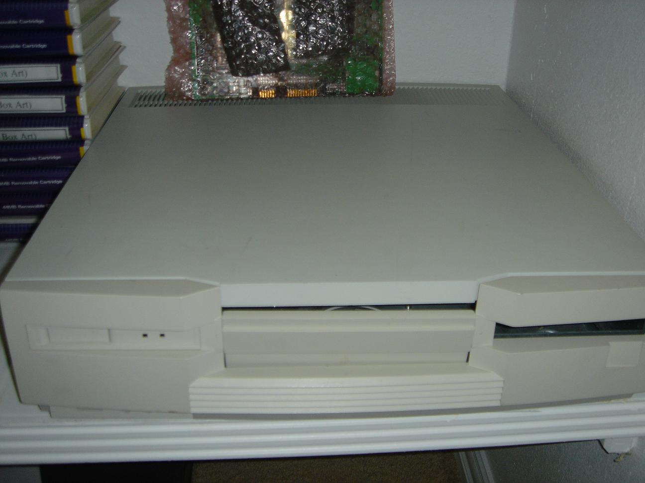
Note: there are two versions of the Microbox case, one having a floppy disk drive on the front-right of the system which was for the machine described above, and a CD-ROM version for the Falcon040.
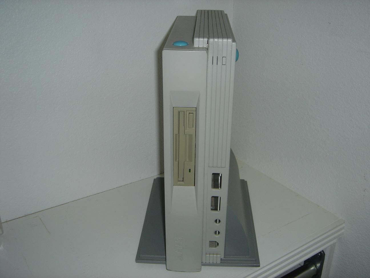

And then there is the Falcon040 itself (designed by the Dallas team). It would seem it was supposed to share a case of similar design as the Microbox but the PCB surely is different - more slots, more sockets for ICs in development.
In Dec’92 the rumours about Atari Corp. having a Falcon040 in development were pretty much alive (with the focus on built-in CD drive), with planned release date in late 1993 as a more powerful successor of the Falcon030. As there is no mention of the Microbox whatsoever, one could think that sometime during the infamous Falcon030 production problems Atari Corp. realised that the Microbox doesn’t make much sense anymore and went ahead with a full 68040 “PC like” machine. However, the Microbox prototype was still being brought up in Jun’93, so both machines seem to have been in development in parallel for quite a while. Unfortunately, no machine was ever shown or previewed in 1993 or later…
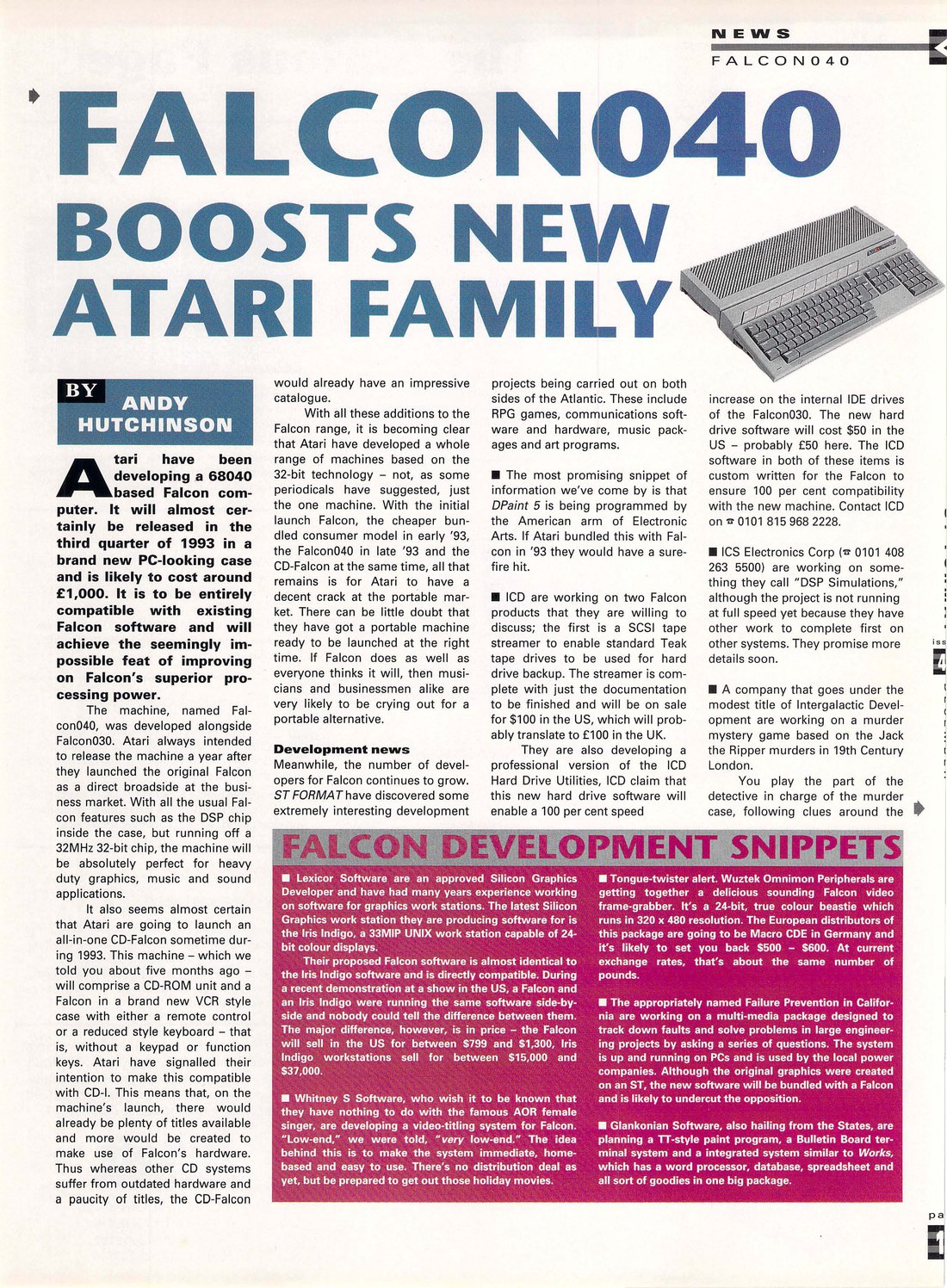
Note: according to Hans Martin-Krober, an Atari employee, the case for the Falcon040 was entirely different.
Who was who
As far as the documents tell:
- Moshe Segal and Eran Dariel (Atari Israel): the Sparrow and its VIDEL and COMBO specifications, the VTG cook book7546
- John D. Horton Jr. (Dallas): the Falcon / Falcon040, the Falcon030’s SDMA specification in Jul’92, the Falcon-A DMA3720
- John Hoenig: SDMA documentation and Falcon030 schematic changes in Jun-Jul’9220
- Tracy Hall (Sunnyvale): Falcon030 schematic changes, also the ST Book hardware specification2040
- Scott Matson: delivered the new VIDEL and COMBEL specifications in Jul’9220
- Scott Lewis: delivered the Falcon040 MCU specification in Sep’9237
- Richard Miller (Sunnyvale): worked on the Sparrow in Dallas, got drawings for the UK developer meeting, ordered the Dallas engineering archive142041
- “RGM”: the FX-1 and Falcon030 hardware reference guides1024
- Roy Stedman and Tom Le: the Sparrow / Falcon030 production diagnostics, Tom Le also the expansion port test fixture818
- Toomey Freeman: the Falcon 030 diagnostic specification18
- Brian St. Denis: Atari Microsystems’ chip layout procedure, using the COMBEL as its example42
- Tom Ulaszek (Dallas product engineering) and Jerry Smith: preparing the Falcon030 production in Taiwan in Jul-Aug’922029
- Marty Pennock (Dallas technical publications): the Sparrow / FALCON030 and Falcon service guides131
- Steven Chan and Ira Valenski: mechanical design questions in the Falcon specification2
- Eric Smith (TOS group, with Hans-Martin and Cary): TOS 4.03/4.04 and MultiTOS in 1993, bringing up the Microbox prototype33
Gallery
My collection of Sparrow photos is available as a gallery here: Sparrow Gallery.
-
TECHPUBS PGSTREAM/F030/F030SERV: “FALCON030 Service Guide” C303062-001, Oct 1 1992 (parts list in F0307.DOC). ↩ ↩2 ↩3 ↩4 ↩5 ↩6 ↩7 ↩8
-
Falcon specification (dated Aug 26 1992), section 10 “Mechanical Considerations” and section 12 “Revisions”. ↩ ↩2 ↩3 ↩4
-
TECHPUBS WP/SPARROW/SDMA.DOC (“Sparrow DMA”, Nov 4 1991) and WP/SPARROW/SDMA.TXT (Jan 1992). ↩
-
TECHPUBS WP/SPARROW/COMBO.A07: “SPARROW - (SP) COMBO SPECIFICATION” rev A7 by Eran Dariel and Moshe Segal, Dec 19 1991. ↩ ↩2 ↩3 ↩4
-
TECHPUBS WP/SPARROW/VIDEL.A05: “SPARROW - (SP) VIDEO CHIP SPECIFICATION” rev A5 by Eran Dariel and Moshe Segal, Dec 19 1991. ↩ ↩2
-
TECHPUBS WP/SPARROW/COOKBOOK.VTG: “VTG Cook Book” rev A2 by Eran Dariel, Dec 12 1991. ↩ ↩2
-
Sparrow specification (dated Dec 18 1991), rev A10 change list and section 2. ↩ ↩2
-
TECHPUBS WP/SPARROW/DIAGS: Sparrow production diagnostics source code, Dec 1991 - Jul 1992 (changelog in VERSION.S, author in SPARROW.S, details in INIT.S, TIMER.S, DMA.S, VIDEO.S, VIDEO.DOC, SDMA.S, CONSOLE.S, DSP.S, KEYBD.S and GENTST.S). ↩ ↩2 ↩3 ↩4 ↩5 ↩6 ↩7 ↩8
-
TECHPUBS EASYDRAW/SUNNYVAL/DSPBOARD.GEM: DSP board drawing, Feb 24 1992 (partly damaged file). ↩
-
TECHPUBS PGSTREAM/F030/HWREF.BAK and PGSTREAM/F030/HWREF.DOC: “FX-1 Hardware reference guide” v0.3 (Feb 16 1992) and v0.4 (Feb 18 1992). ↩ ↩2 ↩3 ↩4 ↩5
-
TECHPUBS PGSTREAM/FAX/ISRAEL2.DOC (Nov 25 1991), ISRAEL3.DOC (Jan 13 1992) and ISRAEL4.DOC (Jan 28 1992): faxes from Atari Dallas to Moshe Segal. ↩ ↩2
-
TECHPUBS PGSTREAM/WEEKLY/TOMU1212.DOC and TOMU1219.DOC: weekly reports, Dec 12 and Dec 19 1991. ↩
-
TECHPUBS PGSTREAM/WEEKLY/TOMJAN9.DOC, TOMJAN16.DOC, TOMJAN23.DOC, TOMJAN30.DOC and TOMFEB06.DOC: weekly reports, Jan 9 - Feb 6 1992. ↩ ↩2 ↩3 ↩4 ↩5
-
TECHPUBS PGSTREAM/FAX/RICHARD2.DOC (fax to Richard Miller, Jan 30 1992) and PGSTREAM/FAX/RICHARD3.DOC (memo to Richard Miller, Mar 4 1992: “while you were here working on the Sparrow project”). ↩ ↩2
-
TECHPUBS DYNACADD/PARTS/DXF/STEPUP.DXF, STEPRT.DXF and STEPLFT.DXF (STE+, Oct 21 1991) compared to EASYDRAW/SPARUPA.GEM and EASYDRAW/SPARRT.GEM (Feb 1992), EASYDRAW/SPARROWL.GEM (Apr 1992) and DYNACADD/PARTS/DXF/SPARROWR.DXF (Feb 7 1992); the STE+ description is from its service manual PGSTREAM/STEPLUS/STEPCH1.DOC. ↩
-
TECHPUBS EASYDRAW/SUNNYVAL/MEMORY50.GEM, MEMORY30.GEM, EXPAND50.GEM and EXPAND30.GEM: “SPARROW MEMORY CONNECTOR” and “SPARROW EXPANSION CONNECTOR”, Feb 20 1992. ↩
-
TECHPUBS PGSTREAM/F030/F030PROD: “FALCON030 Hardware Product Specification” C302550-001 rev B, Aug 10 1992. ↩ ↩2 ↩3 ↩4
-
TECHPUBS PGSTREAM/F030/DIAGNOST.3_3: “FALCON 030 DIAGNOSTIC SPECIFICATION”, preliminary version 00 by Toomey Freeman, Mar 3 1992, with the “FALCON 30 Expansion Test fixture Specification” by Tom Le, Feb 28 1992. ↩ ↩2 ↩3
-
TECHPUBS PGSTREAM/FALC030/INTRO.DOC, GL_MTOS.DOC and GL_GAMES.DOC: developer documentation, Apr 1992. ↩
-
TECHPUBS PGSTREAM/WEEKLY/TOMJUN11.DOC, TOMJUN25.DOC, TOMJUL09.DOC, TOMJUL16.DOC, TOMJUL30.DOC and TOMAUG13.DOC (weekly reports, Jun - Aug 1992) and PGSTREAM/MEMO/TOMSPARQ.DOC (memo to Tom Ulaszek, Jul 13 1992). ↩ ↩2 ↩3 ↩4 ↩5 ↩6 ↩7 ↩8 ↩9 ↩10 ↩11
-
TECHPUBS DYNACADD/PARTS/DXF/SYSEXPAN.DXF: “SYSTEM EXPANSION PCB (SPARROW)”, Jun 9 1992. ↩
-
TECHPUBS EASYDRAW/SPARROWB.GEM: “Overall System Block Diagram”, Apr 6 1992. ↩
-
TECHPUBS PGSTREAM/FALC030/HARDNOTE.DOC: “Developer Hardware Release Notes”, Apr 29 1992. ↩ ↩2
-
TECHPUBS PGSTREAM/TEXT/F030HARD.TXT: “Falcon030 Hardware Reference Guide” v1.0a, May 11 1992. ↩ ↩2
-
TECHPUBS PGSTREAM/TEXT/PSU117R4.TXT: “117 VAC SPARROW PSU SPECIFICATION”, revisions dated Feb 29 - May 18 1992. ↩
-
TECHPUBS WP/SPARROW/SDMA.TXT (Jan 1992) compared to PGSTREAM/TEXT/SDMA.TXT (Jul 1992). ↩
-
TECHPUBS WP/SPARROW/DIAGS/SPARROW3.DOC: “Problems with rev. 3 board”, Roy Stedman, Jul 10 1992. ↩ ↩2
-
TECHPUBS PGSTREAM/CHIPDOCS/COMBEL.DOC: COMBEL specification, Aug 1992. ↩
-
TECHPUBS PGSTREAM/MFG_PROC: “FALCON 030 PRODUCTION PROCEDURE” C302758-001, revision 1 draft, Jul 15 1992. ↩ ↩2 ↩3 ↩4 ↩5
-
TECHPUBS EASYDRAW/F030RGHT.GEM (Jul 23 1992) and DYNACADD/PARTS/F030/F030RGHT.DPT (Jul 24 1992) compared to DYNACADD/PARTS/DXF/STEPRT.DXF. ↩
-
TECHPUBS PGSTREAM/WEEKLY/TOMSEP24.DOC: weekly report, Sep 24 1992. ↩
-
TECHPUBS PGSTREAM/WEEKLY/TOMSEP10.DOC: weekly report, Sep 1992. ↩
-
Eric Smith’s progress reports at atarimania.com, weeks ending Mar 6, Mar 20, May 1, Jun 12 and Jun 26 1993. ↩ ↩2 ↩3
-
TECHPUBS WP/FALCON/FALCON1.TXT: Falcon service guide draft, section one, Jan 1992. ↩
-
TECHPUBS PGSTREAM/TEXT/IO.TXT (“Design specification for the FALCON IO controller”) and PGSTREAM/TEXT/DMA.TXT (“Design specification for the FALCON DMAC”), Feb 1992. ↩
-
TECHPUBS PGSTREAM/TEXT/ADMA.TXT: “Falcon-A DMA ASIC Description”, Jul 1992. ↩
-
TECHPUBS PGSTREAM/FALCON/FALSCHED.DOC (Feb 3 1992) and weekly reports PGSTREAM/WEEKLY/TOMJUN11.DOC, TOMJUL09.DOC, TOMAUG13.DOC, TOMSEP10.DOC and TOMSEP17.DOC (Jun - Sep 1992). ↩ ↩2 ↩3
-
TECHPUBS WP/MEGASTE/ECO.LIS (ECO 1385, Feb 28 1992) and WP/MEGASTE/2MBMGIN.TXT (MEGA STE 2 MB floppy upgrade, Nov 1991). ↩
-
Microbox bill of materials, dated 02-05-1993. ↩
-
TECHPUBS PGSTREAM/MEMO/STRICH1.DOC: memo to Richard Miller, Sep 11 1992. ↩
-
TECHPUBS PGSTREAM/FAX/ISRAEL5.DOC: fax to Eran Dariel and Moshe Segal, Aug 3 1992. ↩
-
TECHPUBS TEMP/DESLAYOT.TXT: “The design - layout interface, use of EHN software” by Brian St. Denis, Dec 16 1991 / Apr 14 1992. ↩