| |

16MB Ram mit umschaltbarem TOS

Inspect the TAB upgrade board for any physical signs of damage or
any bad solder joints. This is just a precautionary measure. The
boards are inspected before packaging, but damage may occur
afterwards.These instructions assume that you are familiar with the
computer and its components and have the computer already
disassembled.
Installation Instructions
- 1.
- Locate the GLUE chip (CO25915) and cut the traces going to pins
4,5,6,7,8. There may be only one trace going to each pin or there may
be 2, depending on the motherboard that you have. These are the
A16-A20 address lines respectively. Each one only goes from the 68000
CPU to the GLUE and MMU (CO25912). On some motherboards, the lines
come from the CPU to the MMU and then on to the GLUE. In this case
there should be only 1 trace to each of the 5 pins on the GLUE chip.
On other motherboards, the lines come from the CPU to the GLUE and
then on to the MMU. In this case there will be 2 traces to each of
these pins (probably 1 on top and 1 on bottom) and both must be cut.
In essence, the pins 4-8 at the GLUE need to be taken out of the
circuit. Isolated and open. Nothing connected to them. Refer to
drawings in back.
- 2.
- If you had to cut more than 5 traces, then you must jumper the
A16-A20 address lines to the MMU from the CPU. A16-A20 are pins 44-48
on the CPU respectively and go to pins 11-15 on the MMU respectively.
Do this on the bottom side of the motherboard. Use 26-30 guage tinned
wire. If you only had to cut 5 traces, then no jumpers are required.
Refer to drawings in back for a visual aid.
- 3.
- If available, use an ohm meter to check the continuity between
the CPU and MMU, and check that there is no continuity to the pins of
the GLUE.
- 4.
- Locate a suitable place to position the TAB board and fan the
first 7 wires to reach pins 44-53 of the CPU. Fan the next 3 wires
(8-10) to reach the last TOS rom in your system. Fan the last 6 wires
(11-16) to reach the GLUE.NOTE: Cut all wires as short as possible to
reach their termination point, within reason. No banjo strings please.
- 5.
- Connect wire 1 (the red one) to the capacitor going to pin 1
(+5v) of GLUE.
- 6.
- Connect wires 2-7 to CPU pins 44-48, and 52 respectively.
- 7.
- Connect wires 11-15 to GLUE pins 4-8 respectively.
- 8.
- Connect wire 16 to the other side of the capacitor where you
connected wire 1.
- 9.
- It's a good idea to test the computer at this point. Place the
motherboard where you would normally place your computer. Make sure it
is on a non conductive surface. Connect monitor, power supply,
keyboard, and optionally your disk drive and turn the power on. The
computer should boot as it would before anything else was done, unless
you don't hook up the disk drive, then it will take a little longer
and go to the desktop without any icons. If all is well, proceed to
next step.
- 10.
- Remove the 6 TOS roms chips, and note where they were installed
for later reference. If you have the 2 chip rom set, simply remove the
old roms and plug the new roms into the sockets, and skip instructions
11-15.
- 11.
- On the 128K x 8 bit roms (2.06) strap and solder pins 1,32,31,
and 30 together. Bend out pins 2 and 3 to about a 45 degree angle.
- 12.
- Install the EO rom in the socket where you removed chip CO26165
(TOS 1.0).
- 13.
- Install the EE rom in the socket where you removed chip CO26162
(TOS 1.0).NOTE: Make sure that the exposed 5 pins (1,2,3,31,32) do not
short out to anything.
- 14.
- Connect wire 8 to pin 3 of both new roms.
- 15.
- Connect wire 9 to pin 2 of both new roms.NOTE: Wire 10 does not
get connected. It is a spare.
- 16.
- Test computer as in step 9. On power up, the Atari logo should
appear and after an added delay (for a hard disk to come up to speed)
it should start a memory test. Press escape key to bypass the memory
test.
- 17.
- If all is well, reassemble computer, or proceed to dual TOS
optional instructions. Dual TOS Instructions (Optional)If for one
reason or another you want to be able to switch between the new TOS
and the old TOS the following is required. Do the normal installation
FIRST. Then follow the following instructions.
- NOTE:
- If your rom chips are under the power supply, you will have to
find some way to raise the power supply about 1/2 inch, or you will
have to remove the sockets the dual roms go into and solder the
original roms to the motherboard. If you raise the power supply, the
case will have to be cut for the plug and power switch. Also the top
cover may not fit good and the extra heat closer to the plastic could
cause the plastic to melt. You will also probably need to modify your
top shield. In other systems check the clearances BEFORE you proceed
with these instructions.
A. 6 chip set instructions
- 1.
- Remove the new roms from the sockets (do not disconnect wires)
and install your old roms back in the sockets, but bending pin 20 of
both old roms out.
- 2.
- Piggyback the new roms on top of the old roms with the exception
of pins 3 and 22. These pins should line up with pins 1 and 20 of the
old roms respectively. It may be easier to piggyback the roms out of
the sockets.
NOTE:
Pins 20 of the old roms and pins 22 of the new roms are the active
low chip select pins and if not in use must be pulled high.
- 3.
- Strap the old roms pins 20 together and connect to +5V through a
10K ohm resistor.
- 4.
- Strap the new roms pins 22 together and connect to +5V through a
10K ohm resistor.
- 5.
- Wire the center post of a SPDT toggle switch to pin 20 of one of
the old rom sockets.
- 6.
- Wire one side of the switch to one of the pins 20 of the old
roms.
- 7.
- Wire the other side of the switch to one of the pins 22 of the
new roms.
- 8.
- Test computer as before. Flip the switch to change the TOS. DO
NOT flip switch with POWER ON. If you do, the system WILL crash.
- 9.
- Reassemble computer, and mount toggle switch in an out of the way
location to avoid accidental switching, but keep it as close to the
roms as possible.
B. 2 chip set instructions
- 1.
- Remove the new roms from the sockets and install your old roms
back in the sockets, but bending pin 22 of both old roms out.
- 2.
- Piggyback the new roms on top of the old roms with the exception
of pin 22. It may be easier to piggyback the roms out of the sockets.
NOTE:
Pin 22 of the roms are the active low chip select pins and if not
in use must be pulled high.
- 3.
- Strap the old roms pins 22 together and connect to +5V through a
10K ohm resistor.
- 4.
- Strap the new roms pins 22 together and connect to +5V through a
10K ohm resistor.
- 5.
- Wire the center post of a SPDT toggle switch to pin 22 of one of
the old rom sockets.
- 6.
- Wire one side of the switch to one of the pins 22 of the old
roms.
- 7.
- Wire the other side of the switch to one of the pins 22 of the
new roms.
- 8.
- Test computer as before. Flip the switch to change the TOS. DO
NOT flip switch with POWER ON. If you do, the system WILL crash.
- 9.
- Reassemble computer, and mount toggle switch in an out of the way
location to avoid accidental switching, but keep it as close to the
roms as possible.
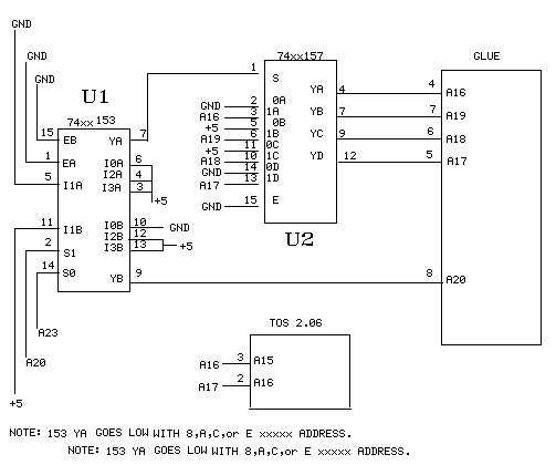
Abbildung 1
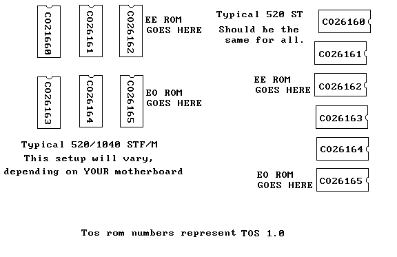
Abbildung 2
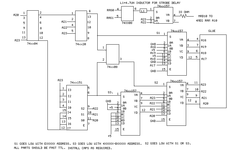
Abbildung 3
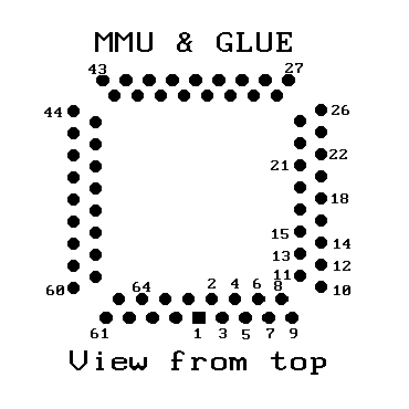
Abbildung 4
Problems
- A.
- If your system doesn't work after you have installed the new
roms, check the following.
- 1.
- Make sure the roms are plugged into the proper sockets. From pin
19 of the GLUE, you should have continuity to both roms pin 22. If
not, you are in the wrong rom socket banks.
- 2.
- Also check that rom pin 24 of the EO rom has continuity to GLUE
pin 46. The EE rom pin 24 should have continuity to GLUE pin 47. If
either of these is wrong, you are in the wrong socket.
- 3.
- The red wire from our board is wire #1, and count sequentially to
16 at the other side of the ribbon cable. Don't confuse wire number
with the pin number on the plug. They DON'T match up. Wire 1 actually
goes to pin 16, wire 2 goes to pin 1, etc. We ALWAYS refer to WIRE
NUMBER.
- 4.
- Double check to make sure all wires are going to proper place and
without shorts.
- 5.
- Did you test the computer at the suggested intervals. If not,
back up and try to isolate the problem.
- B.
- If you use the dual rom option and you are using a TV, and you
experience RF interference, using a shielded cable to the switch will
help. Ground the shield close to the connections to the roms. DO NOT
connect shield to switch.It's more likely to be an incorrect
installation than a bad board. There just isn't much on our board to
fail. We use FAST TTL logic when normal LS would work. The circuit is
proven and rock solid. Check your installation again. We will repair
or replace any defective board returned to us within 1 year of
purchase.Refer to following drawings at back during installation.
TOS 2.06 FEATURES
This list of features has been compiled by us, and is intended as
a guideline for using the new TOS. It IS NOT a complete description of
the DESKTOP, or the TOS 2.06 operating system. It will mention some of
the differences between TOS 1.0 & 2.06.
BOOT UP
On boot up, you will notice there is a delay. This is designed to
give a hard disk a chance to come up to speed. So you can hook your
hard disk & computer to the SAME power switch and turn them on at
the same time now.
If you don't touch the keyboard on power up, the new TOS will
perform a RAM & ROM test of the system. The time required for this
depends on the amount of memory you have. To BYPASS this, simply hit
your Esc key anytime after powerup.
NEWDESK.INF
The new TOS searches for 'NEWDESK.INF' on power up. If this is not
found, it uses the old 'DESKTOP.INF' file. Once you are up and
running, configure your desktop, and SAVE it. It will be saved as
'NEWDESK.INF'. If both files are kept on the boot disk, then it would
be compatible with both the old and new TOS.You will notice some new
commands under the top menu. Here are some brief explanations.
FILESEARCH
Will search the current drive for specified files.
DELETE ITEM
Will delete ALL highlighted items.
BOTTOM TO TOP
Will bring the bottom folder to the top.
SELECT ALL ITEMS
Will highlight ALL items in the current window.
SET FILE MASK
Window will show only files that match this file mask.
VIEWNO SORT
Shows files in th order they are actually in on the disk.
SIZE TO FIT
Will attempt to show all files in window, if ICONS are selected.
SET COLOR & STYLE
Set the color & hatch patterns for the windows & destop.
OPTIONSINSTALL ICON
Allows ICONS to be installed in window or desktop.
INSTALL APPLICATION
First HIGHLIGHT the application program. Allows you to install an
application with many different parameters. To place on a function
key, type Fn where it ask 'Install as:'. F11-F20 is using Shift + Fkey
Click on 'Auto' if you want this program to run on bootup. Put
document type (.TXT, .SRC, .ARC, etc.) in ONLY if you want this
program to run ANY TIME you open one of these type files. Put in any
arguments you want passed to the application when it is ran.
INSTALL DEVICES
Does a system check and installs icons for All devices found. (!nl
READ .INF FILE
As you may have guessed you can have as many different desktop
configurations as you want. This let's you read a new one in.
CAUTION
When configuring your different desktops, rename the one you want
to boot with temporarily. Any time you save the desktop, it's goes to
'NEWDESK.INF' and WILL overwrite the existing one. Once you have
configured all your desktops, and changed their names to what you
want, change the name of your original back to 'NEWDESK.INF'.
DESKTOP CONFIGURATION
Set your default directory (normally=applicaiton) and input params
(normally=Full path). Shows your function key assignments, if any. And
last but not least, lets you assign single keystrokes to do all the
functions in the top menu. HELP KEYPress the help key to display many
more keystroke features of the new TOS. You will learn more by playing
with these than I could tell you in a few pages.
PUTTING FILES ON THE DESKTOP
You can now put ANY FILE right on the desktop. What does this
mean? Well, once you put a file on the desktop, you won't have to open
a window to run it. Simply highlight and drag the file out of the
window and onto the desktop. Any time you want to run the file, just
double click on the icon. No more going through windows to get to it.
While the function keys are limited to 20 (F1-F20), this is limited to
only the size of the desktop. You can have 32 icons on a medium res.
screen. You can also put ANY file on the desktop, even folders. click
on a destop folder and a window of that folder will open. You can also
edit the shape of any icon on the desktop to more reflect what it is.
REMEMBER to SAVE your desktop after ANY configuration change, or it
will be lost the next time you boot.
XCONTROL.ACC AND CPX'SXCONTROL.ACC
is the new control panel. It requires that the .CPX files be
availible to it for it to run properly. They are in the CPX folder on
the disk. Once installed, you will need to configure it. You may
already have a control panel that you use, and XCONTROL.ACC IS NOT
REQUIRED to use the new TOS. Try it and see if if works better for you
than the one you are using. I have included several SHAREWARE programs
on the disk. If you decide to use these, please contribute to the
authors request.
I don't know anything about the author but the manual sounds good

Copyright © Robert Schaffner (doit@doitarchive.de)
Letzte Aktualisierung am 23. Mai 2004
|